Usage of Graphical Editors
There are some general mechanisms that apply to all graphical editors for particular models. We cover these mechanisms in the following. For specific aspects of specific graphical editors, please refer to the descriptions listed in the Overview.
Opening Graphical Editors
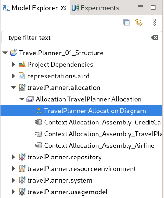
Fig. 3 Model Explorer with expanded allocation model
There are multiple ways to open the graphical editor for a certain model.
The simplest way is to expand the model contents in the Model Explorer up to the second level as shown in Fig. 3. On the second level, there will be an entry for the graphical diagram, whichs name usually indicates that it is a diagram. By doing a double-blick on that entry, a graphical editor will open. If such an entry does not exist, there is no graphical diagram for the particular model.
Creating Elements
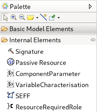
Fig. 4 Partial palette of repository model
Every editor contains a palette on the right hand side consisting of multiple tools that you can use to create elements. In order to create an element, select it and click in the appropriate location within the diagram. If you cannot click at a certain location, the element cannot be created there. You should choose another location to create it.
By holding the ctrl key while clicking in the diagram, the selected tool will stay selected. This is useful if you create a large amount of elements of the same type. By pressing esc, you can disable the selected tool at any time.
Viewing Semantic Properties of Diagram Elements
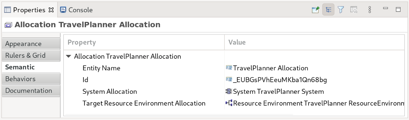
Fig. 5 Properties view showing semantic properties of an allocation
Often, relevant properties can be changed by inline-editing within the editor. However, some properties of elements are only available via the so-called Properties view. To show the properties for an element, you first have to select it in the editor and then go to the properties view.
The contents of the view depend on the selected object. On the left side of the view, there is a list of tabs grouping various properties. Again, the shown tabs can vary but there will always be a Semantic tab as shown in Fig. 5. This tab shows the properties of the selected element as they are represented in the underlying model. You can change many of these properties.
Warning
Please be aware that there are usually no sanity checks for the changes you do in the properties view. An invalid change can even break parts of the graphical editor or can render your model useless. Therefore, only do changes in the properties view if you are asked to do so or you are completely sure about your changes.