Analyzing Attack Propagations
Scientific Background
Screencast for Attack Propagation
Analysis Execution
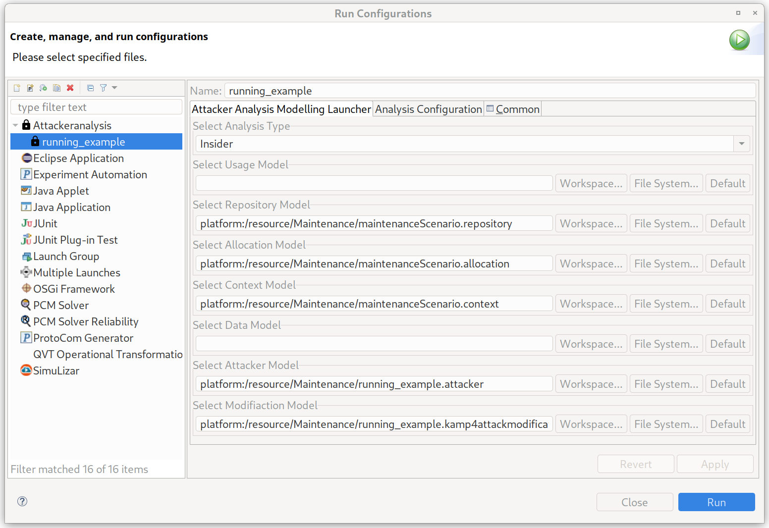
The analysis can be started via an Eclipse launch configuration. The launch configuration name is Attackeranalysis. It can be created in Eclipse by clicking Run->Run Configurations. This opens a dialog similar to the example image below. There Attackeranalysis can be selected (right side). There you can create a new launch config. Now please select as analysis type Insider and select the correct models. For the insider analysis, we need the Repository Model, Allocation Model, Context Model, Attacker Model, and Modification Model. The model can be selected either as reference from the workspace (recommended) or from the file system.
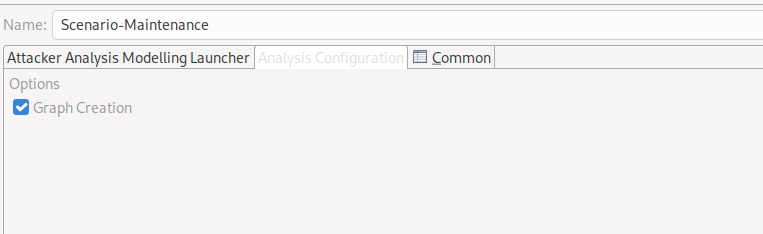
The analysis can be configured to create besides the EMF output model also an image of the attack graph. This can be done by changing to the Analysis Configuration tab. There you can check the box for graph creation. If the graph creation is enabled, the analysis will automatically generate a PNG image withing the model folders.
Note
The graph creation uses internally Graphviz. Please make sure to add the Graphiz binary to the path variable of the Java environment.
Analysis Results
There are two results files for the attack propagation possible. The first is the modification mark model and the second is the attack graph image.
Modification Mark Model
In the kamp4attackmodificationmarks model the regular output is stored. It contains two elements. The KAMP4AttackSeedModifications where the attacker for the propagation is selected. The actual output is then stored in the CredentialChange element. It contains a list of compromised architectural elements.
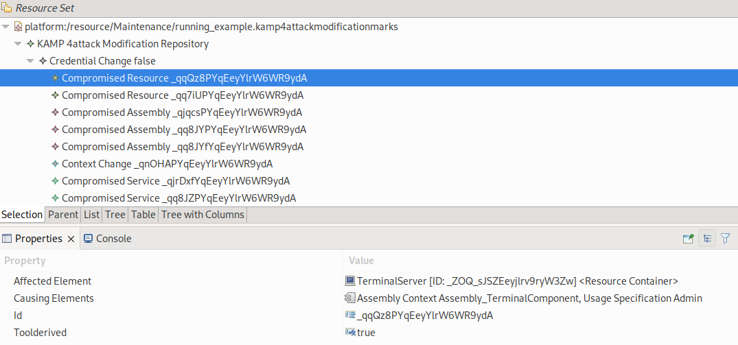
The screenshot shows an excerpt of the output model for the Maintenance Scenario (Running Example). It shows the compromised architectural elements. In our case, we selected (blue) the first compromised resource. In the properties view the additional properties are show. The Affected Element shows which architectural element is compromised (here TerminalServer). The Causing Elements show the source and reason for the compromisation. Here the attacker attacked from the TerminalComponent by using the Admin credentials. Every architectural element in this field is the source of the attack. Vulnerabilities or credentials (UsageSpecification) are the reasons. The ID is the unique ID of the element. The last element is Tool Derived. It indicates, that the element is automatically derived from our analysis. If the value is false it is from the initial configuration.
Note
The model also contains container for dynamically created elements. Since in EMF every modelled must be contained in one container, we need to store these dynamically generated model elements somewhere. They cannot be stored in the originally models, therefore we contain them here.
Attack Graph Image
By activating the graph creation, our analysis produces an attack graph. The image shows the attack graph from the Maintenance Scenario (Running Example).
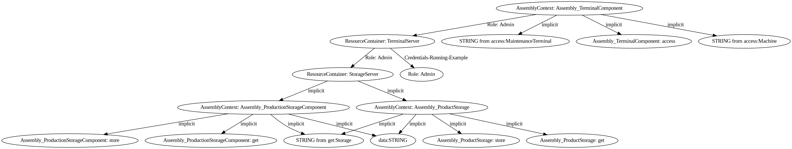
Each node is either an architectural element, data element or role. The type is indicated with the textual description. Architectural elements are always “Type: Name”. The types are AssemblyContext, LinkingResource, or ResourceContainer. Data elements are either “datatype from instantiated Service” for return values from services or “Name: parametername” for parameter values. Credentials are indicated by “Role: name”.
The edges contain the reason for compromising an element. An element can be compromised by using credentials, vulnerabilities or implicit. The propagation by credentials is indicated by “Role: name”. For vulnerabilities only the name is written on the edge. Implicit propagations use our assumptions. For instance in our example is that by compromising a component all data is affected.
Note
Despite that it might be assumed by the graphical representation, the graph does not always show the order of the attack propagation. It only shows the affected element and by which element it was affected.